


Jeep 4-way tire inflation/deflation
- Jun 19, 2018
- 6 min read
I built a custom centralized air system for my 2011 Jeep Wrangler Unlimited so that I could inflate or air-down all four tires at once. When you take a Jeep (or any capable vehicle) off road, it's a good idea to partially deflate the tires. Airing them down increases the contact area with the ground which results in better traction and grip. It also allows the tire to flex more and conform to terrain such as rocks. This also gets you better grip.
On road, I run my 37" Goodyear MTR/Kevlar tires at 30 PSI. When I take the Jeep offroad, I decrease that to usually between 12 and 15 PSI. You could use the back side of a tire gauge to press the valve pin in and let air out. That would take FOREVER. Some people use a common valve tool to take out the valve core to let some air out. This works really fast, but there is a very good chance the valve core will slip out of your fingers and rocket past your head, never to be seen again. Trust me, I know about this one first hand. Here is the tool I have been using: an ARB EZ deflator. This tool works great. It removes the valve core for quick air release, but also keeps it safely trapped in the tool and includes a gauge for hitting the target pressure in each tire. The downside to any of these methods is the time it takes to go from tire to tire, checking and rechecking until you get each one right.
I built a system that allows me to deflate all 4 tires at once, have them all equalized to the same pressure, all while I'm doing other tasks like disconnecting my sway bar or getting my beef jerky and other supplies in the front seat where I can reach them.
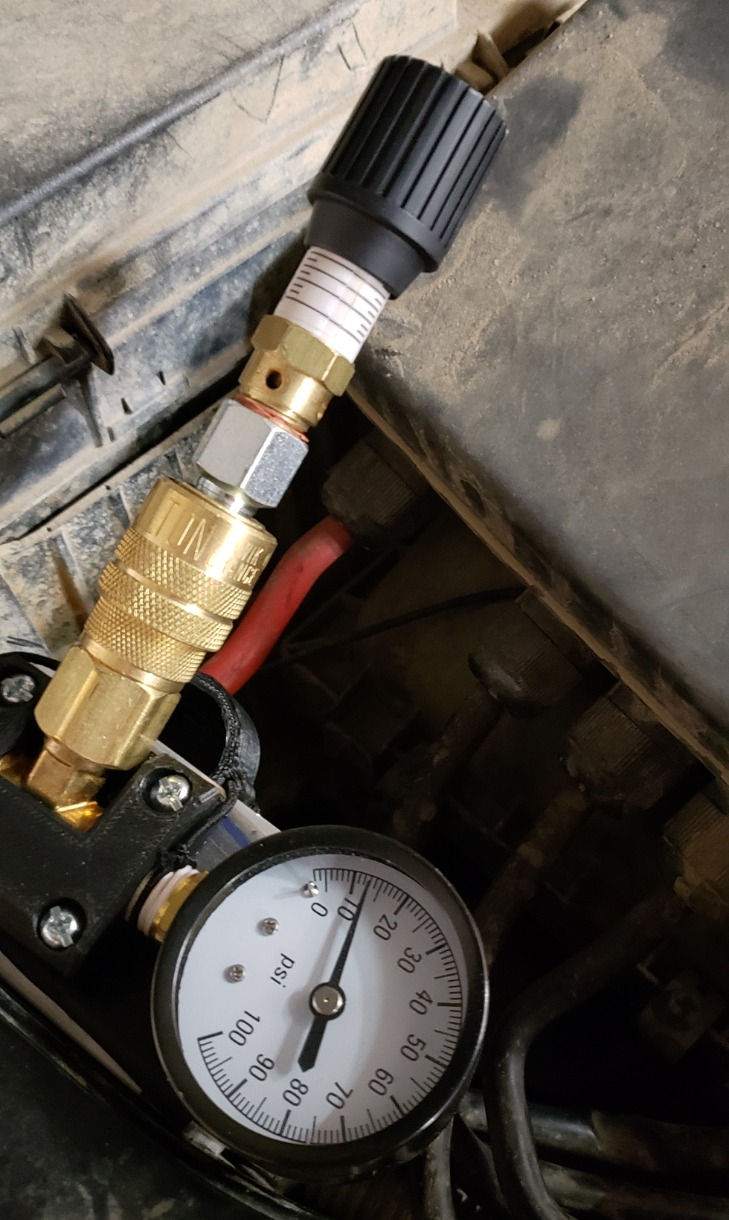
The first part of the system I built was the gauge and air chuck that goes in the engine bay:

The gauge and tee are generic pieces I got at Menards. The chuck is a Milton #715 coupler that I had from a pack I bought to outfit my garage. I have several of these coupler kits and none of them have ever leaked or given me any problems. I highly recommend them.
I designed and 3D printed the ABS plastic mount block. It angles the coupler upward slightly and keeps everything locked in place. It is attached to a short section of 2" aluminum angle stock that I had on hand. The angle is attached to the inner fender wall with two sheet metal screws. I also 3D printed a cap to keep dirt and crud out of the coupler.
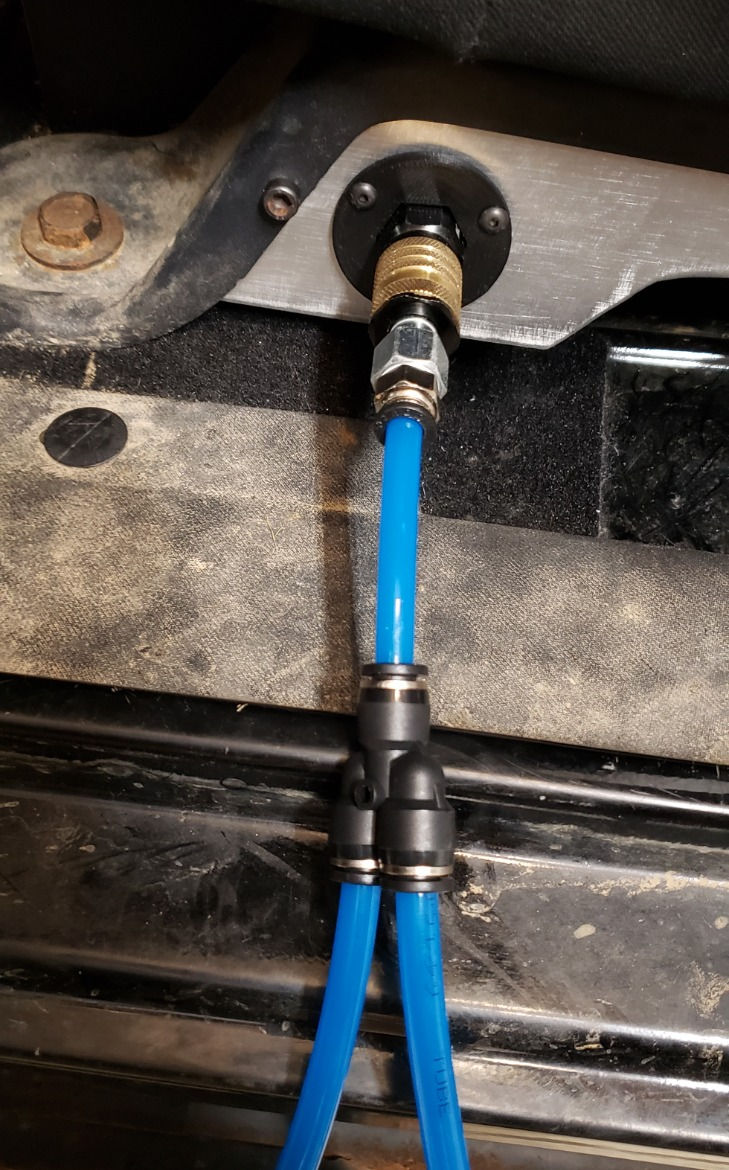
All of the plumbing is all made up of Polyurethane Air Tube and push-lock fittings. The 8 mm air line runs through a foam-filled hole in the lower A-pillar into the cabin. It runs down along the end of the dash behind the trim panel and then behind the kick panel and door trim, exiting under the passenger front seat. A push-lock splitter separates the line for driver and passenger sides. Under each seat is a push lock elbow connected to a quick coupler. A straight connector might have worked, but I have storage boxes under both seats and didn't like the angle the hose had to bend in order to fit. The 90 degree elbow fixed that issue. I chose to use a different coupler at this point. I really like the Miltons, but I wish they were push-to-connect. I couldn't find any standard I or M-style couplers that you could push the plug into without having to pull the lock ring back first. I think that is only available on Universal-style couplers. I bought two of these at Menards and they work well and do not leak at all. If they give me trouble in the future, I'll replace them with Miltons.
Building the interior mounts
The next step was to make a mount for the connectors. I started with a scrap of cardboard to make a template. I cut the pattern out of some scrap aluminum C-channel. The channel is part of an old 2-post telecom mounting rack.


I had to stop several times during the cutting process. I was using my Harbor Freight angle grinder and the aluminum was really soaking up the heat. It got too hot to hold, even with light gloves, several times during the cutting and shaping process.

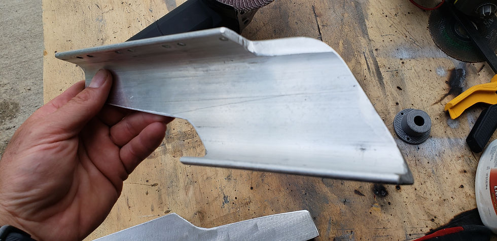
All of the edges and corners were eased over so there were no razor sharp surprises under the seat.
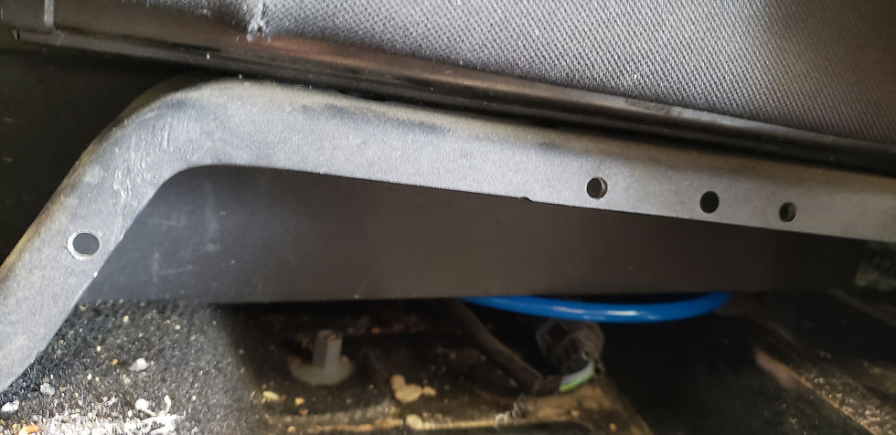
There are three holes in the seat frame along the top edge. For some reason, two of them are smaller. I drilled out the two smaller holes to match the larger one and then drilled one more matching hole on the front leg.
I held up the aluminum piece to the frame to mark the hole positions and then drilled and tapped the holes.
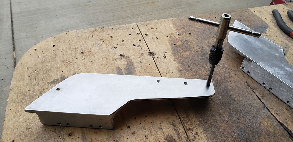
I temporarily mounted the panel to the seat so I could figure out where to mount the air coupler.

The hole was drilled out to 1-1/4" using a step bit. I used the plastic mounting bezel that I designed and 3D-printed to mark the screw hole locations. They were drilled and tapped.

Finally it was time to mount the air coupler fixture in the bracket and attach it to the seat.

The aluminum is pretty soft. I didn't want to tighten the screws too much and risk stripping out the threads. Instead, I opted to put a tiny amount of blue loctite on all of the screws to keep them from backing out.
I am still debating painting the bracket. Right now, I like the contrasting color of the silver aluminum.
Hooking up the tires
To connect the tires to the system, I made two Y-hoses, also known as "whips". Each one has a male quick coupler that plugs into the under-seat connector. The same 8 mm Poly tubing connects to another splitter. There is 8 more feet of Poly tubing to reach each tire. At the end of each 8 foot tube is a clip-on air chuck to connect to the tire valve stem. I am currently testing two different chuck types to see which one I like best. Here is the first set, and here is the second. If one turns out to be a problem, I'll replace those two with the better one.
When you connect all 4 tires to the system, they will auto-level to the same pressure, equalizing through the tubing until all are the same pressure.

Airing down the tires
To deflate the tires, I just have to plug a pressure release valve into any of the quick couplers. The release valve can be adjusted to any desired pressure. It is similar to a safety relief valve on any compressor. It releases air until the target pressure is reached and then the valve closes. I can monitor progress using the pressure gauge I built into the system.
Re-inflating the tires
Pumping all of the tires back up to street pressure the old way is time consuming as well. You have to babysit the compressor for each tire. The gauges built into those compressors are notoriously unreliable. When the compressor is running, the gauge might show 45 PSI, but when you turn it off, the real pressure is only 28, as an example. So you're always turning off the compressor to check inflation progress. And the compressor switch and the pressure gauge are not in the same spot. The switch is on the motor, and the gauge is at the tire. It's just tedious.
With my new 4-way system, I can inflate all of the tires at once and they'll all end up at the exact same pressure. I just plug the compressor into the quick-coupler under the hood and turn it on. I have the Smittybilt high volume compressor, and it takes just over 8 minutes to inflate all 4 tires from about 13 PSI back up to 30. That's about the same time it takes to inflate all four individually, but it takes much longer from start to finish when you count in the time lost to checking pressure on each tire plus disconnecting from one tire and moving on to the next. This way is much more efficient. While this is running, I can reconnect my sway bars and put away any other gear I used in preparation for leaving the offroad park.
This setup uses universal connectors for all of the connection points. I could easily be used with compressors from ARB, Viair, etc or even a CO2 power tank system.
“We are a participant in the Amazon Services LLC Associates Program, an affiliate advertising program designed to provide a means for us to earn fees by linking to Amazon.com and affiliated sites.”
Comments